Solderless prototyping
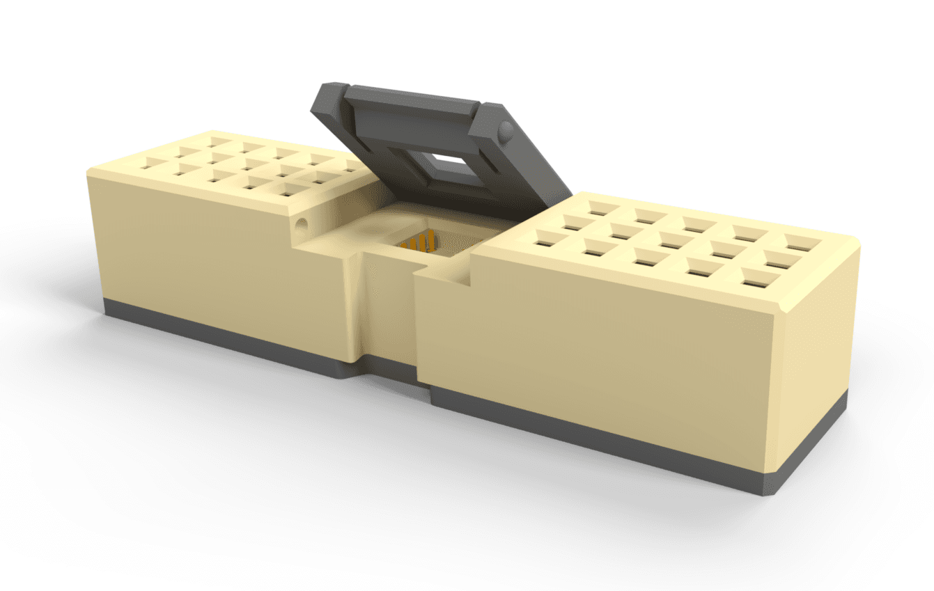
Snap-in sockets and tile-to-breadboard adapters bring true plug-and-play to the bench — pads arranged left-to-right make wiring multi-tile systems fast and intuitive, with no soldering and no damage to the tile.

 BERGSONNE
Overview
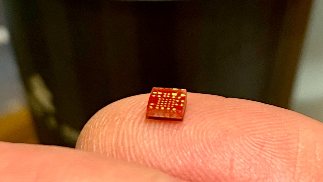
A tile is a fully integrated electrical subsystem — the IC, its passives, and its support circuitry — encapsulated into a standardized, surface-mountable package with a common electrical interface. The hard parts of embedded design are solved once, validated, and sealed inside; what's left outside is a handful of coarse-pitch pads.
Families
Every tile belongs to a color-coded family that names what it does. Within a family, tiles share driver conventions and documentation structure; across families, they share the same package, pads, and bus.
Microcontroller brains — program them over USB or SWD, with ROM-DFU recovery built in.
— in production · — in beta
Motion, pressure, light, touch, and environmental sensing — the inputs from the physical world.
— in production · — in beta
Motor drivers, haptic drivers, and audio amplifiers — outputs with muscle.
— in production · — in beta
Wired and wireless connectivity — buses, radios, and bridges to everything else.
— in production · — in beta
Regulation, battery charging, and power-path management for every rail.
— in production · — in beta
Non-volatile memory and storage for data that has to survive a power cycle.
— in production · — in beta
LEDs and light output — indicators and displays that give a product a face.
— in production · — in beta
Every tile, filterable by family, function, and status — with datasheets, pad maps, and driver links.
Browse the catalog →Mechanical
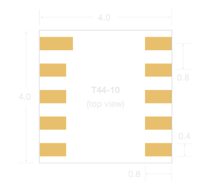
Tiles ship in the T44 and T48 package families — epoxy-encapsulated blocks with surface-mount pads along the left and right edges. Orientation reads from the marking dot on top and the extended first pad underneath.
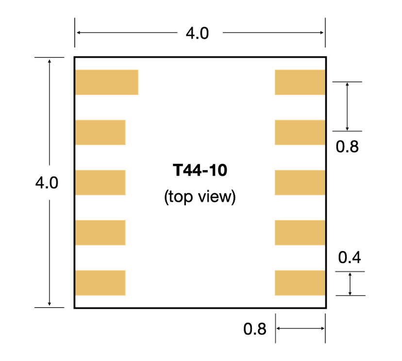
The baseline T44-10: a 4.0 × 4.0 mm body with ten pads at a 0.8 mm pitch, 1.0–2.0 mm tall depending on the components sealed inside. The epoxy encapsulation makes the tile mechanically robust — tiles survive handling, breadboarding, rework, and reuse across the prototype-to-product lifecycle.
| Package | Body | Pads | Drawing |
|---|---|---|---|
| T44-10 | 4.0 × 4.0 mm | 10 | PDF ↓ |
| T44-12 | 4.0 × 4.0 mm | 12 | PDF ↓ |
| T44-14 | 4.0 × 4.0 mm | 14 | PDF ↓ |
| T48-16 | 4.8 × 4.8 mm | 16 | PDF ↓ |
| T48-22 | 4.8 × 4.8 mm | 22 | PDF ↓ |
Electrical
The electrical standard is what makes tiles interchangeable: power and the bus are always in the same place, so any tile drops onto any carrier that speaks the standard.
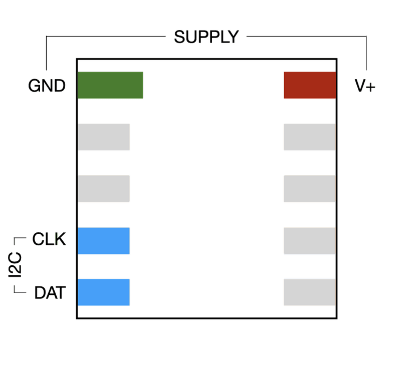
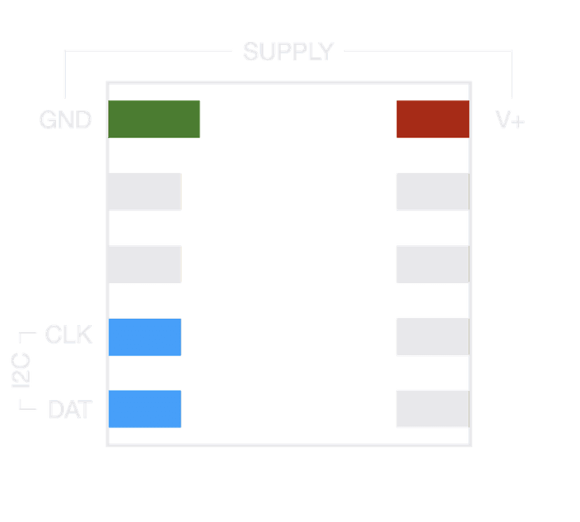
GND and VDD anchor the corners; the I3C/I²C bus sits on pads 4 and 5. The six remaining pads are the tile’s own — SPI, analog, interrupts, triggers, and GPIO, documented per tile in the catalog.
| Pad | Signal | Notes |
|---|---|---|
| 1 | GND | Ground — common to every tile |
| 2 | Tile-specific | SPI, analog, interrupt, or GPIO |
| 3 | Tile-specific | SPI, analog, interrupt, or GPIO |
| 4 | SCL | I3C / I²C clock |
| 5 | SDA | I3C / I²C data |
| 6 | Tile-specific | SPI, analog, interrupt, or GPIO |
| 7 | Tile-specific | SPI, analog, interrupt, or GPIO |
| 8 | Tile-specific | SPI, analog, interrupt, or GPIO |
| 9 | Tile-specific | SPI, analog, interrupt, or GPIO |
| 10 | VDD | Supply — common to every tile |
Full per-tile pad maps live in pad assignments, and bus address allocation in the I²C address registry.
Resources
Generated from the canonical tile definitions, so they stay in step with the hardware.
Default and alternate I²C addresses for every tile — the allocation map that keeps multi-tile buses conflict-free.
View the registryThe default function of each pad on every tile, with its alternates — the full per-tile matrix behind the common pad map above.
View the matrixIntegration
The coarse pad pitch is a deliberate choice: it keeps tiles compatible with home- and classroom-grade tools at every stage — solderless prototyping first, then simple carriers you can make on cheap equipment.
Snap-in sockets and tile-to-breadboard adapters bring true plug-and-play to the bench — pads arranged left-to-right make wiring multi-tile systems fast and intuitive, with no soldering and no damage to the tile.
With all the complexity inside the tile, carriers stay simple: single-sided, 0.4 mm traces, printable, laser-etchable, or fabbable on entry-level equipment. Attach with solder or conductive adhesive — and reverse it for effortless reuse.
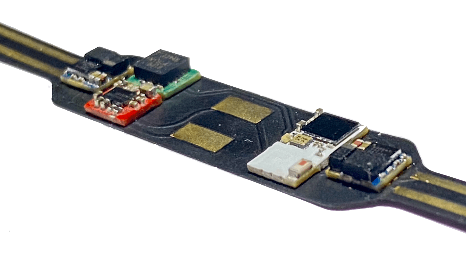
Footprints, schematic symbols, and 3D models for every package — exactly as they land in your ECAD tool — ready to drop into your own carrier designs.
Firmware
Every tile ships with an open-source driver that handles register maps, data conversion, and protocol details. Drivers talk to hardware through a thin platform abstraction layer — bring the bus, and the driver does the rest.
Studio
Compose a tile system in the browser, wire up behavior, and run it on simulated hardware — digital twins of every tile, down to the power rails. When it works, build the firmware and flash it over USB.
Open Studio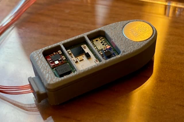
Reference designs
From a compact haptic ring to multi-sensor wearables — fully documented builds with carriers, firmware, and BOMs, ready to fork as starting points for your own products.
Explore designs